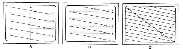
Figure 13-4.–Video scanning.
Figure 13-4 illustrates how this scanning process takes
place. The electron beam first scans all odd-numbered
lines, from left to right (a). When all odd-numbered lines
have been scanned, it makes up a field. One field
consists of 262.5 lines. After the odd-numbered ones are
scanned, the beam jumps back to the top of the screen.
At this point, the beam is so weak that it does not affect
the screen. Back at the top of the screen the beam starts
scanning the even-numbered lines (b). When all
even-numbered lines are scanned a second field is
formed. The two fields make up a frame (c) or one
complete television picture. A frame consists of
525 lines. After completing a frame, the beam returns to
the top to start with another first field.
This charge-forming-and-scanning is a fast,
continuous process. The complete camera tube screen
(frame) is scanned 30 times per second.
The motion-video camera picks up reflections of
light from the scene while the microphone picks up
sound. At the same time, the camera changes the light
reflections into electrical impulses, and the microphone
changes the sound into electrical impulses.
This is basically the way a black-and-white video
camera works. A color video camera works on the same
principle; however, a color video camera has three
tubes. Through the use of a beam splitting device and
filters, one tube forms a red image, a second tube forms
a green image, and the third tube forms a blue image.
The three tubes have identical scanning patterns, so the
picture signals they produce are identical, except they
differ in color.
During a video recording, the videotape moves past
a rotating head that “writes” the video and audio signals
on the videotape. During playback, the rotating head
“reads” the magnetically stored information off the tape
Some VTRs use two or four heads for their record/play
(write/read) functions. Digital VTRs have even more
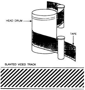
Figure 13-5.–Helical scanning system.
read/write heads. For explanation purposes a VTR with
two record/play heads is discussed in this chapter.
Helical, or Slant-Track, System
The two heads are mounted opposite each other,
either on a rapidly spinning head drum or on a bar that
spins inside a stationary head drum. When the bar spins
inside a stationary head drum, the heads contact the tape
through a slot in the head drum. The tape is wound
around the head drum in a slanted, spiral-like manner.
This permits more tape area to contact the head,
allowing the transfer of large amounts of video
information (fig. 13-5). If the head contacted only the
width of the tape, extreme tape or drum speed would be
necessary. Because the Greek word for spiral is helix,
this tape wrap, and often the whole video-recording
system, is called the helical scan, or slant track
13-7