possible error in lining up each successive flight line.
The longer dimension of the film is always used for the
GGS.
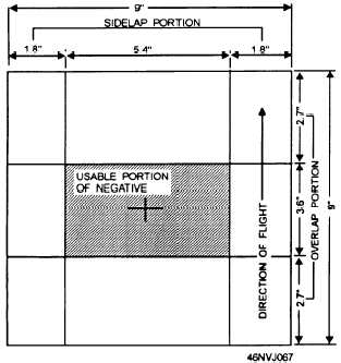
Figure 4-20 shows the usable portion of a 9-
9-inch negative after the GGF and GGS have been
factored in.
NUMBER OF EXPOSURES
When you are flying for mosaic mapping purposes,
the flight strips are usually made along the long
dimension of the area being photographed. This
practice reduces the number of turns the aircraft must
make to photograph the strips. For example, if the area
to be photographed is 5 nautical miles east and west by
10 nautical miles north and south, the strips should be
flown north and south.
To determine the number of exposures per strip, you
should divide the ground-gained forward into the length
of the map. When the unit of measurement is in nautical
miles, you must convert it into feet (1 nmi = 6,080 ft).
Therefore, if the area to be photographed is 10 nautical
miles, the area when converted to feet is 60,800 (10
6,080).
You add four additional frames to each strip. Two
additional photographs should be taken just before
reaching the beginning point and two just after the
ending point. These four photographs allow for
possible errors in reading the beginning point and the
Figure 4-20.—Usable portion of a 9- 9-inch negative.
ending point of the run on the ground (from the data
shown on the flight chart).
You must first calculate the total number of flight
strips required to cover the area. Next, divide the
ground-gained sideways (GGS) by the total width of the
area to determine the total number of strips. Always
add one additional strip to your calculations. To
determine the total number of photographs (frames)
required for the entire mosaic mission, multiply the
number of photographs required for each strip by the
number of strips.
If the camera can hold enough film for the entire
mission, you should have no problem. However, if the
camera does not hold enough film for the entire mission,
you either have to change film between strips or be
prepared to make several flights.
FLIGHT LINES
Before the mapping flight, you should plot the flight
lines for each run and draw them on the flight chart with
a color that is easily recognizable. Draw the first flight
line along the border of the area to be photographed.
The remainder of the flight lines should be evenly
spaced and parallel to one another.
Figure 4-21 shows a nomograph that can be used to
determine the number of flight lines required to cover
the target. This nomograph is for low-altitude coverage
only.
The nomograph (fig. 4-21) is used as follows:
1. Place a straightedge on the width of the area to
be searched and another along the altitude to be flown.
2. Note the intersection on line R1.
3. Place a straightedge on the point on R1 and
another along the field of view of the camera lens.
4. Note the intersection on line R2.
5. Move to R3, keeping the same relative positions
on segments R1 and R2.
6. Place a straightedge on the point on R3 and
another along the side lap required.
7. Read the number of flight paths (to the largest
whole number).
To determine the distance between the plotted lines
on the chart, you must change the ground-gained
sideways into inches and multiply it by the scale
(fraction) used on the chart. For example, if the GGS
is 5,400 feet, or 64,800 inches, and the scale of the chart
4-22